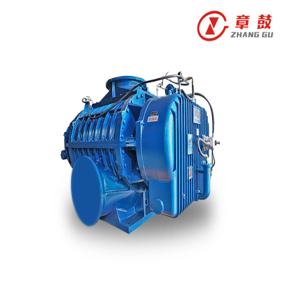
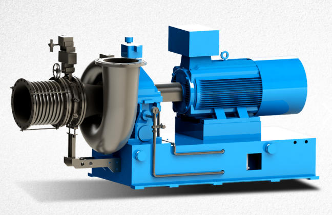
High speed centrifugal fan
1.The impeller is designed using three-dimensional flow theory, and flow analysis technology is adopted to predict the performance of the blower, achieving variable efficiency up to 82%.
2. The fan is equipped with axial guide vanes at the inlet and a diffuser adjustment device. The flow adjustment range is from 45% to 110% of the nominal flow, allowing for efficient operation even under conditions deviating from the design specifications.
3. An integrated design is used, with the blower housing mounted on the speed increase box housing. The lubrication system, electric motor, and speed increase box are compactly located on a common base, which also serves as the oil tank.
4. The rotor undergoes strict dynamic balancing, ensuring low vibration, high reliability, and low overall noise levels. Thanks to its low moment of inertia, the unit has short acceleration and shutdown times. Compared to multi-section centrifugal blowers with the same flow and pressure, it consumes less energy, is lighter, and takes up less space.
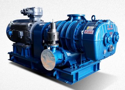
centrifugal fan High speed
1.The impeller is designed using three-dimensional flow theory, and flow analysis technology is adopted to predict the performance of the blower, achieving variable efficiency up to 82%.
2. The fan is equipped with axial guide vanes at the inlet and a diffuser adjustment device. The flow adjustment range is from 45% to 110% of the nominal flow, allowing for efficient operation even under conditions deviating from the design specifications.
3. An integrated design is used, with the blower housing mounted on the speed increase box housing. The lubrication system, electric motor, and speed increase box are compactly located on a common base, which also serves as the oil tank.
4. The rotor undergoes strict dynamic balancing, ensuring low vibration, high reliability, and low overall noise levels. Thanks to its low moment of inertia, the unit has short acceleration and shutdown times. Compared to multi-section centrifugal blowers with the same flow and pressure, it consumes less energy, is lighter, and takes up less space.


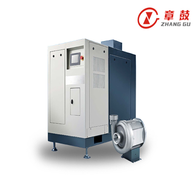
Intelligent control solution for centrifugal blowers
As a key equipment in the chemical industry, the stable operation of centrifugal blowers is especially important to ensure safe production and protection of key equipment. Due to the complex operation process, the control system often controls individual equipment; To realize loading and unloading, it usually requires many steps to be performed manually, which sometimes makes it difficult to accurately control the equipment according to current needs. By separately controlling the inlet guide vanes (IGV) and the vent valve (BOV), it realizes the one-button loading and unloading function of the centrifugal blower, and offers two control modes: automatic re-adjustment and constant pressure adjustment. This improves the intelligence and reliability of the control system, and solves the problem of accurately controlling the centrifugal blower according to current needs. ...
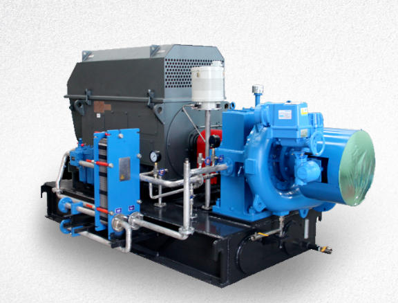
It improves the intelligence and reliability of the control system, and solves the problem of accurately controlling the air centrifugal fan according to the actual needs of process production. [2] Starting conditions for centrifugal fans Starting conditions for centrifugal fans are generally divided into conditions such as lube oil cooler downstream temperature above 35°C, lubricating oil main pressure above 0.25 MPa(G), fan inlet guide vane (IGV) position slightly open, blower vent valve (BOV) position fully open, unit stopped without locking, and start allowed from DCS. [2] Loading and Unloading Process of Centrifugal Fans Loading Process The loading process of a compressor is the process of transitioning from unloaded (no load) condition to constant pressure control until the set pressure is reached and air is supplied to the system. When the set pressure of the system is higher than the operating pressure...
When the system set pressure is higher than the actual pressure, the intake vanes will gradually open from 10% idle and the engine current will begin to increase. When the current exceeds 230A (TL set value), begin to close the small exhaust valve, and the intake guide vanes will be adjusted together with the exhaust valve to keep the motor current at 230A until the pressure in the three stages rises and the system pressure reaches the set value and enters the constant pressure maintenance mode. The speed of this loading process and the success of its implementation depend on the magnitude of the proportionality coefficient and the integrated control time. When the system demand is large, the integrated time should be increased to achieve the set pressure rate. On the contrary, when the system demand is small, it should be reduced, otherwise the response will be too sensitive, resulting in valve oscillation and instability, and the loading process may fail.
.